Packet Tracer – Troubleshooting Challenge – Document the Network (Answers Version)
Answers Note: Red font color or gray highlights indicate text that appears in the instructor copy only.
|
Device |
Interface |
Device Type |
IP Address |
Subnet Mask |
Default Gateway |
|
PC1 |
NIC |
Host |
192.168.1.153 |
255.255.255.0 |
192.168.1.1 |
|
PC2 |
NIC |
Host |
192.168.3.50 |
255.255.255.0 |
192.168.3.1 |
|
PC3 |
NIC |
Host |
192.168.4.115 |
255.255.255.0 |
192.168.4.1 |
|
PC4 |
NIC |
Host |
192.168.5.83 |
255.255.255.128 |
192.168.5.1 |
|
PC5 |
NIC |
Host |
192.168.5.227 |
255.255.255.128 |
192.168.5.129 |
|
PC6 |
NIC |
Host |
192.168.2.48 |
255.255.255.224 |
192.168.2.33 |
|
PC7 |
NIC |
Host |
192.168.2.67 |
255.255.255.224 |
192.168.2.65 |
|
Hub |
G0/0/0 |
router |
192.0.2.1 |
255.255.255.252 |
N/A |
|
Hub |
S0/1/0 |
router |
192.168.0.1 |
255.255.255.252 |
N/A |
|
Hub |
S0/1/1 |
router |
192.168.0.5 |
255.255.255.252 |
N/A |
|
Hub |
S0/2/0 |
router |
192.168.0.9 |
255.255.255.252 |
N/A |
|
Hub |
S0/2/1 |
router |
192.168.0.13 |
255.255.255.252 |
N/A |
|
Branch-1 |
G0/0/0 |
router |
192.168.1.1 |
255.255.255.0 |
N/A |
|
Branch-1 |
S0/1/0 |
router |
192.168.0.2 |
255.255.255.252 |
N/A |
|
Branch-2 |
G0/0/0 |
router |
192.168.2.33 |
255.255.255.224 |
N/A |
|
Branch-2 |
S0/1/0 |
router |
192.168.0.6 |
255.255.255.252 |
N/A |
|
Factory |
G0/0/0 |
router |
192.168.3.1 |
255.255.255.0 |
N/A |
|
Factory |
G0/0/1 |
router |
192.168.4.1 |
255.255.255.0 |
N/A |
|
Factory |
S0/1/0 |
router |
192.168.0.14 |
255.255.255.252 |
N/A |
|
HQ |
G0/0/0.1 |
router |
192.168.6.1 |
255.255.255.0 |
N/A |
|
HQ |
G0/0/0.5 |
router |
192.168.5.1 |
255.255.255.128 |
N/A |
|
HQ |
G0/0/0.10 |
router |
192.168.5.128 |
255.255.255.128 |
N/A |
|
HQ |
S0/1/0 |
router |
192.168.0.10 |
255.255.255.252 |
N/A |
|
SW-B1 |
VLAN 1 |
switch |
192.168.1.252 |
255.255.255.0 |
192.168.1.1 |
|
SW-B2 |
VLAN 1 |
switch |
192.168.2.62 |
255.255.255.0 |
192.168.2.1 |
|
SW-F1 |
VLAN 1 |
switch |
192.168.3.252 |
255.255.255.0 |
192.168.3.1 |
|
SW-F2 |
VLAN 1 |
switch |
192.168.4.252 |
255.255.255.0 |
192.168.4.1 |
|
SW-HQ1 |
VLAN 1 |
switch |
192.168.6.252 |
255.255.255.0 |
192.168.6.1 |
|
SW-HQ2 |
VLAN 1 |
switch |
192.168.6.253 |
255.255.255.0 |
192.168.6.1 |
|
SW-HQ3 |
VLAN 1 |
switch |
192.168.6.254 |
255.255.255.0 |
192.168.6.1 |
In this lab, you will document a network that is unknown to you.
- Test network connectivity.
- Compile host addressing information.
- Remotely access default gateway devices.
- Document default gateway device configurations.
- Discover devices on the network.
- Draw the network topology.
Your employer has been hired to take over the administration of a corporate network because the previous network administrator has left the company. The network documentation is missing and needs to be recreated. You job is to document the hosts and network devices including all the device addressing and logical interconnections. You will remotely access network devices and use network discovery to complete a device table and draw the network topology.
This is Part I of a two-part series of activities. You will use the documentation that you create in this activity to guide you as you troubleshoot the network in Part II, Packet Tracer – Troubleshooting Challenge – Using Documentation to Solve Issues.
As you investigate and document the network topology, make note of issues that you discover that do not adhere to the practices taught in the CCNA curriculum.
Part 1: Test Connectivity
Ping between the PCs and the internet server to test the network. All PCs should be able to ping one another and the internet server.
Part 2: Discover PC Configuration Information
Go to the command prompt of each PC and display the IP settings. Record this information in the documentation table.
Part 3: Discover Information about the Default Gateway Devices
Connect to each default gateway device using the Telnet protocol and record information about the interfaces that are in use in the table. The VTY password is cisco and privileged EXEC password is class.
C:\> telnet IP_address
Part 4: Reconstruct the Network Topology
In this part of the activity, you will continue recording information about the devices in the network in the Addressing Table. In addition, you will start to diagram the network topology based on what you can discover about the device interconnections.
Step 1: Access Routing Tables on Each Gateway Device.
Use the routing tables in each router to learn more about the network. Make notes of your findings.
Step 2: Discover Non-Gateway Devices.
Use a network discovery protocol to document neighboring devices. Record your findings in the addressing table. At this point you should also be able to begin documenting device interconnections.
Part 5: Further Explore Device Configurations and Interconnections
Step 1: Access Device Configurations.
Connect to the other devices in the network. Gather information about the device configurations.
Step 2: View Neighbor Information.
Use discovery protocols to increase your knowledge of the network devices and topologies.
Step 3: Connect to Other Devices.
Display configuration information for the other devices on the network. Record your findings in the device table.
By now you should know about all the devices and interface configurations in the network. All rows of the table should contain device information. Use your information to reconstruct as much of the network topology as you can.
You may have noticed that some of the practices used to configure the network devices are out-of-date, inefficient, or not secure. Make a list of as many recommendations that you have regarding how the devices should be reconfigured to follow the practices that you have learned in the CCNA curriculum.
End of document
The list is a lengthy one. This question provides you with an opportunity to review many of the best practices that have been covered in the CCNA curriculum. Use student discussions to ensure that as many issues have been discussed as possible. Some issues are:
- All devices use the same simple and well-known passwords. These should be changed, should vary between devices, and should be stronger.
- The switches all use the default SVI and management VLAN. This should be changed.
- Most switchports are in VLAN 1. They should be moved to different VLANs.
- All unused switchports are in VLAN 1 and are active. Unused switchports should be shut down and moved to an unused VLAN.
- Port security is not in use.
- OSPF is active on LAN interfaces. Passive interfaces will decrease unnecessary network traffic.
- DTP negotiation is active on trunk ports. This is a security risk.
- SSH is not in use in the network.
- Management access to all devices are not restricted using ACLs or AAA.
- 802.1x is not implemented.
- IP Source Guard is not implemented
- CDP is on by default and should be turned off or restricted.
- DTP is active on all ports on SW-B1, SW-F1, SW-F2, SW-HQ1, SW-HQ2 and SW-HQ3 except those ports connected to PC-4 and PC-5.
- Legacy STP is in being used on all switches and should be changed to RSTP (802.1w).
- Native VLAN 1 is being used on trunk links and should be changed.
- VLAN 99 is created only on SW-B2 only. It is not being used and does not have a name and should be removed.
- The hub router has the ip default-gateway command set and the IP address is to itself.
Network Topology Diagram
Students drawings will differ in layout; however, the device interconnections should be consistent. The hidden topology is shown below.
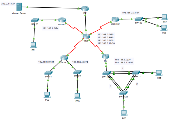
Other items missing in the Topology documentation include the following:
VLANs and port memberships
DTE / DCE devices
DNS Server addresses
OSPFv2 Area
Physical interfaces and associated IP addresses
Physical switchports and associated VLAN / trunking
Each Switch Management VLAN and IP address
STP is being blocked on SW-HQ2 going to SW-HW3
EtherChannel is using LACP (802.3ad)